


May 2013. With the arrival of some warmer weather we’ve been able to get outside and start building the baseboards. Both Pulborough and Brighton Road used 12mm ply, for sides, ends and tops and are cross-braced from corner to corner with more 12mm ply. At 900mm wide and 1200mm in length (longer for Pulborough) they are heavy and awkward to move around. The boards for Plumpton are smaller (1200 by 600 mm) and I’ve decided to use 9mm ply, except for the ends which will be 12mm.
The most important elements of baseboard design are: to prevent the boards twisting; to make sure that the tops don’t sag, and to make sure that the ends are true, square and level (so that the rail joints across the baseboards are trouble-free).
 The corner to corner bracing on Brighton Road has prevented twist and sag, but caused a few problems when trying to fit point motors under the baseboards -
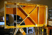
 and finding that the bracing is in the way. For Plumpton I’ve developed a slightly different approach. I have used cross-bracing , but it isn’t corner to corner. The photo of the underside of one of the boards shows what I have done. In this example, the bracing is central, but it could have been moved in either direction to avoid crossings and signals etc, and would still deliver the aim of preventing twist. It also provides support to the board top to prevent sag, and the other (perpendicular) struts provide further support.
This method of bracing also provides support for the baseboard sides, which can thus be thinner (9 rather than 12mm thick).
I’ve kept the ends at 12mm because these need to be absolutely flat to ensure a good joint, and also need to be thick enough to fix the dowels (obtained many years ago from the EM Gauge Society).
June 2013. With two baseboards complete we can now start laying track - a year to the day from when we started the layout. There are many approaches to laying track, and I think I’ve tried most of them, with greater or lesser degrees of success.
For Pulborough we used a cork underlay, fixed down with PVA, and then glued the track in place (with PVA), and then finally ballasted with granite using dilute PVA (with a little detergent to reduce surface tension) dropped onto the ballast. This worked ok but is very slow to do, fairly noisy in operation, and heavy. Dropper wires were fixed after the track had been laid, but before ballasting.
For Brighton Road we used a different approach. The underlay was camping mat (in the hope of reduced noise). Track was laid and ballasted simultaneously using PVA. This is possible with plastic underlay because the PVA doesn’t soak in and dry immediately - there is enough time to lay and align the track, and then apply the ballast. Finally, dropper wires were added. We used granite ballast again.
I’m not sure whether Brighton Road is much quieter than Pulborough, but the downside of camping mat is that it is not very stable, and we have had particular problems with rail joints across base-board joints.
 For Plumpton, I’ve reverted to cork for the underlay to provide better base-
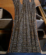
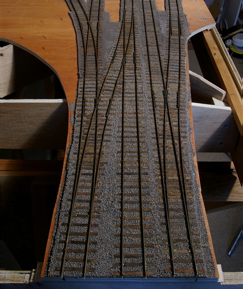
board joints, but fixed down with synthetic latex glue (used for flooring) which doesn’t set hard like PVA. The track has then been glued down with the same adhesive, and because it dries very slowly, there is plenty of time to add ballast - this time using Carr’s and Greenscenes products (crushed nutshells I think) which is very light (in weight) and better colours I think. Before each track panel was laid we fixed the dropper wires, and drilled holes in the base-boards to suit.
It remains to be seen whether the use of synthetic latex glue and lightweight ballast is quieter than PVA and granite - it certainly should be. Laying track and ballasting at the same time is certainly quick - we have laid and ballasted all the track on two base-boards in just two weeks, complete with dropper wires.
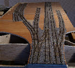
 All the track has been built on Templot templates, and I was a bit concerned that I would damage the track removing the paper templates, and particularly that the turnouts would lose their shape because they use interlaced sleepering which is inherently less rigid than more ‘modern’ trackwork using full length sleepers. My fears were not realised -
 using Pritt stick to fix the sleepers to the templates has been successful in that the template can be removed easily (much better than double sided sellotape). I think also that painting the track edges helped fix the functional chairs to the rail, and hence kept the turnouts reasonably rigid.
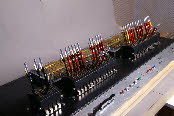 The lever frame is also now complete, with the addition of the section controls and other switches at the front. I can now start wiring up all the levers, switches and cables, so that we can test the track, turnouts and signals as they are added to the layout.
July 2013. Lots of progress this month across all fronts.
Firstly we have finished wiring the control panel and lever frame. This has been quite an extensive task, fitting opposing diodes to all the microswitches in the lever frame (to give half-wave rectified AC, positive or negative, depending on the throw of the lever, to drive point and signal motors one way or the other). All the section switches and AJ magnet push buttons have been wired in, and I have also made made up all the cables connecting the lever frame/control panel to the layout, using 25 way ‘D-connectors’ for control wiring, and DIN connectors for power (15V AC, 5V AC and 21V DC) and earth. I have two earth networks on the layout, one for trackwork, and one other ‘technical ‘ applications.
We’ve also built the third of four baseboards. This has been a bit more complex than the first two because it features an accommodation crossing under the railway (in reality a ‘green lane’). This is now ready for laying track (which was built a while ago), so we’ve been able to start fitting dropper wires to the track ready to start laying in the next few days.
The first two base-boards have fully wired up by Chris and are functional. All the trackwork is operable and Tortoise motors have been fitted for point operation. With everything wired up and connected together, we’ve been able to run the first loco on the layout, and check out the operation of parts of the lever frame (ie the bits on the two baseboards so far completed). Everything works fine from an electrical perspective, and the trackwork looks pretty good so far - just a couple of places where the rail joints are not properly aligned, and one section causing mysterious derailments, perhaps due to gauging problems. However, nothing to be concerned about at this stage, and all can be fixed once the other two baseboards are fully functional.
We’ve also fitted and wired up the AJ magnets on these boards. For Brighton Road we used some electromagnets made by another railway club (can’t remember which) which were effectively homemade. These have proved to be less than reliable at uncoupling, and only work about 50% of the time. In particular, they are not strong enough to uncouple a wagon from a loco, where the loco has a short, fixed coupling. In these circumstances, there is very little side movement available on the loco coupling, and hence quite a lot of down-force is required to reliably uncouple.
Sometime ago I bought an electromagnet from Wizard Models (MSE) with the intention of experimenting with it on Brighton Road. Unfortunately the core of the magnet only protrudes 13 mm above the base plate. The total track-base thickness for Brighton Road is about 25 mm (plywood plus camping mat), so the core is nowhere near long enough. Plumpton on the other hand has a 9mm ply top plus 3mm cork, so the 13 mm long core is not a problem.
The instructions say that the magnets are designed to work with 6-12V DC. I tried 6V DC (using a bridge rectifier with the 5V AC supply), but this did nothing at all. I then tried the the 21V DC supply with various power resistors, progressively reducing the resistance until I got to about 12V. This proved rather difficult, since these magnets have very low resistance, and hence draw a high current. At a voltage of about 12V these magnets seem to draw about 2A and since my transformer is not able to deliver 2A, the voltage drops very rapidly and everything gets rather hot. I still didn’t get very reliable results.
I finally decided to try the 15V AC supply using a power diode to give half-wave rectification. In theory this should deliver about 7.5V average, well within the capacity of the coil. This proved very successful on all fronts: the magnets successfully and reliably uncouple locos, and the average current drawn is only about 0.5A - well within the capability of my transformer, and the coil itself. The main point here is that although the average voltage and current (and hence wattage) are fairly low, the peak voltage should be about 21V (momentarily) and this is enough to uncouple the most stubborn of couplings.
The only downside is that the AJ’s ‘chatter’ because of the half-wave power, and make a bit of a noise. I can hear this in my workroom, but I doubt that it could be heard at all in an exhibition environment. With a bit more experimentation, I found that a 4R7 power resistor in series with the coil reduces the voltage and current drawn a bit further, (and hence make the uncoupling a little quieter), but doesn’t materially affect the reliability of the uncoupling.
My mechanism for operating ground signals for Brighton Road has proved reasonably ok, but is not 100% reliable. A couple of the motors have failed completely, and a couple of others are rather noisy. For Plumpton I think I will revert to more conventional motors - probably some Fulgarex point motors left over from another project.
Brighton Road is 3ft wide and is operated from both front and back of the layout. Whilst we were at the Bluebell MRS recently, it occurred to me that Plumpton could be operated very successfully from the front of the layout. Having spent a long time building the interlocked lever frame, it seems a bit of a shame to hide it behind the layout where nobody can see it. An obvious solution is therefore to simply turn the layout round, so that what was the back of the layout, becomes the front, spectators’ side. The only material difference is which side the back scene has to be fitted to. Plumpton is due to be shown at the Bluebell MRS next June for its first outing, so it will be operated from the front as an experiment.
The most important elements of baseboard design are: to prevent the boards twisting; to make sure that the tops don’t sag, and to make sure that the ends are true, square and level (so that the rail joints across the baseboards are trouble-
 The corner to corner bracing on Brighton Road has prevented twist and sag, but caused a few problems when trying to fit point motors under the baseboards -
This method of bracing also provides support for the baseboard sides, which can thus be thinner (9 rather than 12mm thick).
I’ve kept the ends at 12mm because these need to be absolutely flat to ensure a good joint, and also need to be thick enough to fix the dowels (obtained many years ago from the EM Gauge Society).
June 2013. With two baseboards complete we can now start laying track -
For Pulborough we used a cork underlay, fixed down with PVA, and then glued the track in place (with PVA), and then finally ballasted with granite using dilute PVA (with a little detergent to reduce surface tension) dropped onto the ballast. This worked ok but is very slow to do, fairly noisy in operation, and heavy. Dropper wires were fixed after the track had been laid, but before ballasting.
For Brighton Road we used a different approach. The underlay was camping mat (in the hope of reduced noise). Track was laid and ballasted simultaneously using PVA. This is possible with plastic underlay because the PVA doesn’t soak in and dry immediately -
I’m not sure whether Brighton Road is much quieter than Pulborough, but the downside of camping mat is that it is not very stable, and we have had particular problems with rail joints across base-
 For Plumpton, I’ve reverted to cork for the underlay to provide better base-
It remains to be seen whether the use of synthetic latex glue and lightweight ballast is quieter than PVA and granite -
 All the track has been built on Templot templates, and I was a bit concerned that I would damage the track removing the paper templates, and particularly that the turnouts would lose their shape because they use interlaced sleepering which is inherently less rigid than more ‘modern’ trackwork using full length sleepers. My fears were not realised -
 The lever frame is also now complete, with the addition of the section controls and other switches at the front. I can now start wiring up all the levers, switches and cables, so that we can test the track, turnouts and signals as they are added to the layout.
July 2013. Lots of progress this month across all fronts.
Firstly we have finished wiring the control panel and lever frame. This has been quite an extensive task, fitting opposing diodes to all the microswitches in the lever frame (to give half-
We’ve also built the third of four baseboards. This has been a bit more complex than the first two because it features an accommodation crossing under the railway (in reality a ‘green lane’). This is now ready for laying track (which was built a while ago), so we’ve been able to start fitting dropper wires to the track ready to start laying in the next few days.
The first two base-
We’ve also fitted and wired up the AJ magnets on these boards. For Brighton Road we used some electromagnets made by another railway club (can’t remember which) which were effectively homemade. These have proved to be less than reliable at uncoupling, and only work about 50% of the time. In particular, they are not strong enough to uncouple a wagon from a loco, where the loco has a short, fixed coupling. In these circumstances, there is very little side movement available on the loco coupling, and hence quite a lot of down-
Sometime ago I bought an electromagnet from Wizard Models (MSE) with the intention of experimenting with it on Brighton Road. Unfortunately the core of the magnet only protrudes 13 mm above the base plate. The total track-
The instructions say that the magnets are designed to work with 6-
I finally decided to try the 15V AC supply using a power diode to give half-
The only downside is that the AJ’s ‘chatter’ because of the half-
My mechanism for operating ground signals for Brighton Road has proved reasonably ok, but is not 100% reliable. A couple of the motors have failed completely, and a couple of others are rather noisy. For Plumpton I think I will revert to more conventional motors -
Brighton Road is 3ft wide and is operated from both front and back of the layout. Whilst we were at the Bluebell MRS recently, it occurred to me that Plumpton could be operated very successfully from the front of the layout. Having spent a long time building the interlocked lever frame, it seems a bit of a shame to hide it behind the layout where nobody can see it. An obvious solution is therefore to simply turn the layout round, so that what was the back of the layout, becomes the front, spectators’ side. The only material difference is which side the back scene has to be fitted to. Plumpton is due to be shown at the Bluebell MRS next June for its first outing, so it will be operated from the front as an experiment.