


November 2012. Trackwork proceeds apace, and three out of four boards are virtually complete – nearly all Chris’s work. Functional chairs are being glued in place as we progress, but there will be a lot of work fixing the cosmetic chairs (to hide the rivets).
The ground frame lever frame is coming together very slowly. It really isn’t very good. The cast levers are perhaps the best available (rather than sweated together etched components) but the geometry of the frame is simply wrong, and the design is such that it will be very difficult to assemble. The design of the catchboxes is very poor – I’ll throw these away and scratchbuild something better.
My photos from Lens have arrived. I have some of them already, but these prints are large and good quality, so more detail shows. I have a second view of the station from the west, which shows a bit more detail of the missing building on the down platform. I’ve concluded that this is the original station building from when the line was opened. (This assumption was later proved incorrect - it was a goods lock-up shed). I’ve drawn the building as best I can from what I can see, and within a few days I have another building carcass awaiting painting and windows.
December 2012. Trackwork on all four boards is now almost complete apart from the last few switch rails and check rails. We need to check that all the functional chairs are properly glued down.
Once the trackwork is finished we need to think about tie-bars. For Brighton Road I used separate lengths of 0.5mm brass wire soldered to each of the switch rails, with a gap in between (so that they cannot touch and short circuit), with a piece of very small diameter PTFE tube, of appropriate length to keep the switch blades to gauge, joining the two bits of wire. Tie-bars seem to fail most often because they are too rigidly fixed to the rails, and cannot resist the constant twisting stresses as the blades are moved. My system is reasonably flexible, and has given relatively little trouble on Brighton Road. Now, what have I done with the PTFE tubing?
 I’ve finally got the ground frame lever frame to first base -
 ie mostly complete and operational, except for the redesign of the catchboxes. I’ve fixed it to the locking frame – and hey presto it sort of functions – needs a bit more work though. The turnouts will be operated electrically using Tortoise motors or similar, and I’ve found a neat way of fitting microswitches into the frame to operate when the levers are reversed.
Another walk with a camera and a tape measure, and I have the dimensions of the main station building. A few more days and I have a drawing and then the walls of the building cut-out and ready to assemble.
January 2013. Trackwork is now all in place, and we now have the task of grinding down the rivets so that the cosmetic chairs can be glued in place. This is not my favourite task, but we have at least minimised the effort required by maximising the use of functional chairs. With two of us working together we’ve managed to add the cosmetic chairs to two of the boards – so about 50% complete in a month.
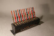
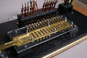
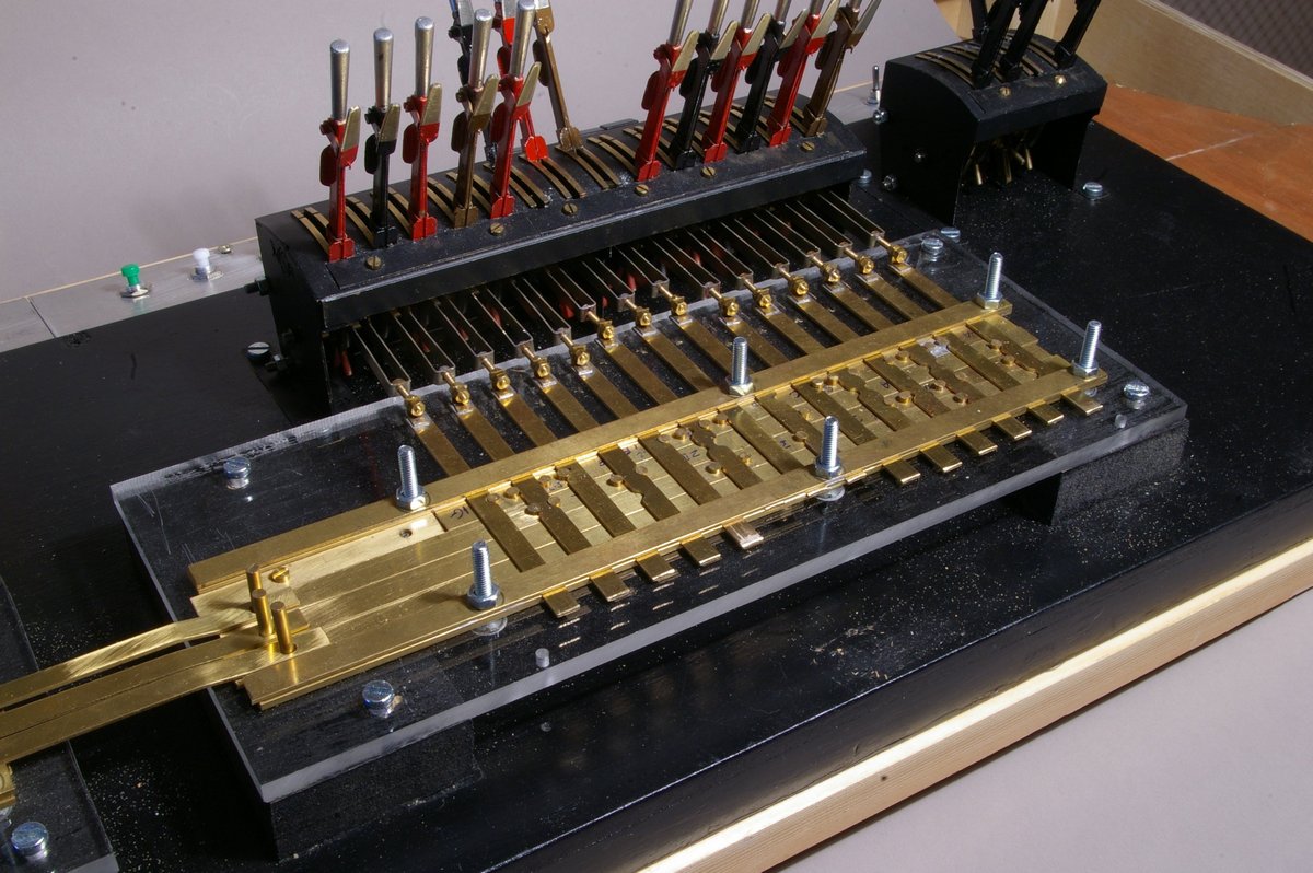
 I’ve more or less finished the carcass of the lever frame for the main box (18 levers) by cutting and joining the 14 lever and 7 lever MSE frames, and adding a few scratchbuilt
 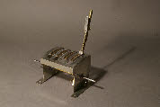 elements (quite a lot actually). I’ve also decided to build a small 4 lever frame for the locally operated points, mimicking the main lever frames, but without interlocking. The main outstanding bit is to redesign the catchboxes, and work out the final assembly.
I’ve sorted out the lifting tappets and sequential locking for the running signals which is all that’s stopped me making the signal box locking frame. Perhaps unnecessary, but I’ve included all the running signals in both directions (home, platform starter, advanced starter as well as distant) in the lever and locking frames, even though only three of these eight signals will be on the scenic section. The off-scene signals will be somehow shown on the fiddle yards probably using LEDs, so that the fiddle-yard operators can see for example that the distant is off, and that therefore the road is clear through to other fiddle yard.
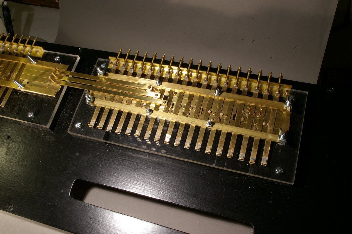
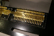 A few day’s work and the main box locking frame is complete and functional together with the locking bars between the two frames.
All I have to do now is sort out the design for the catchboxes, and finish building the lever frames.
February 2013. We were aiming to complete the addition of the cosmetic chairs this month, and we’re almost there. Three and a half boards have been completed, and there’s not much more to do on the last board.
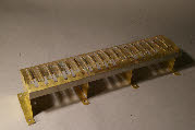
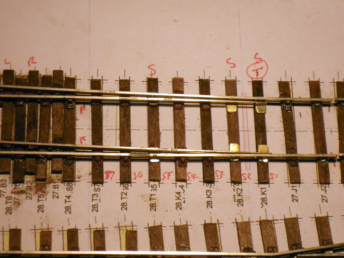
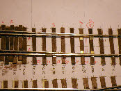 Maintaining gauge along the length of the turnout switch blades can be a bit of a problem so I’ve decided to use some of Bill Bedford’s brass slide chairs. We’ll use one either side of the tie bar (to avoid melting the plastic slide chairs when the tie bars are soldered in place), together with another one or two along the length of the switch rail. All the others will be C&L plastic slide chairs. The photo shows the brass and plastic slide chairs.
I’ve finally sorted out the catchbox design for the lever frame, so I think I’m on the home run with the lever frames. Both the locking frames have been fitted into their final positions, and I’ve attached the signal box lever frame, and satisfied myself that everything will work when I finally assemble the whole lot.
However, having assembled the signal box lever frame with its locking frame, I’ve come to the conclusion that the drive mechanism connecting the levers to the tappets (using 1mm diameter wire) is not positive enough - there’s too much spring in the mechanism, so that it’s not entirely clear whether a lever is locked, or whether it’s just a bit stiff to move. This seems to be a recipe for disaster if anybody unfamiliar with the locking sequence tries to pull a locked lever - something will break.
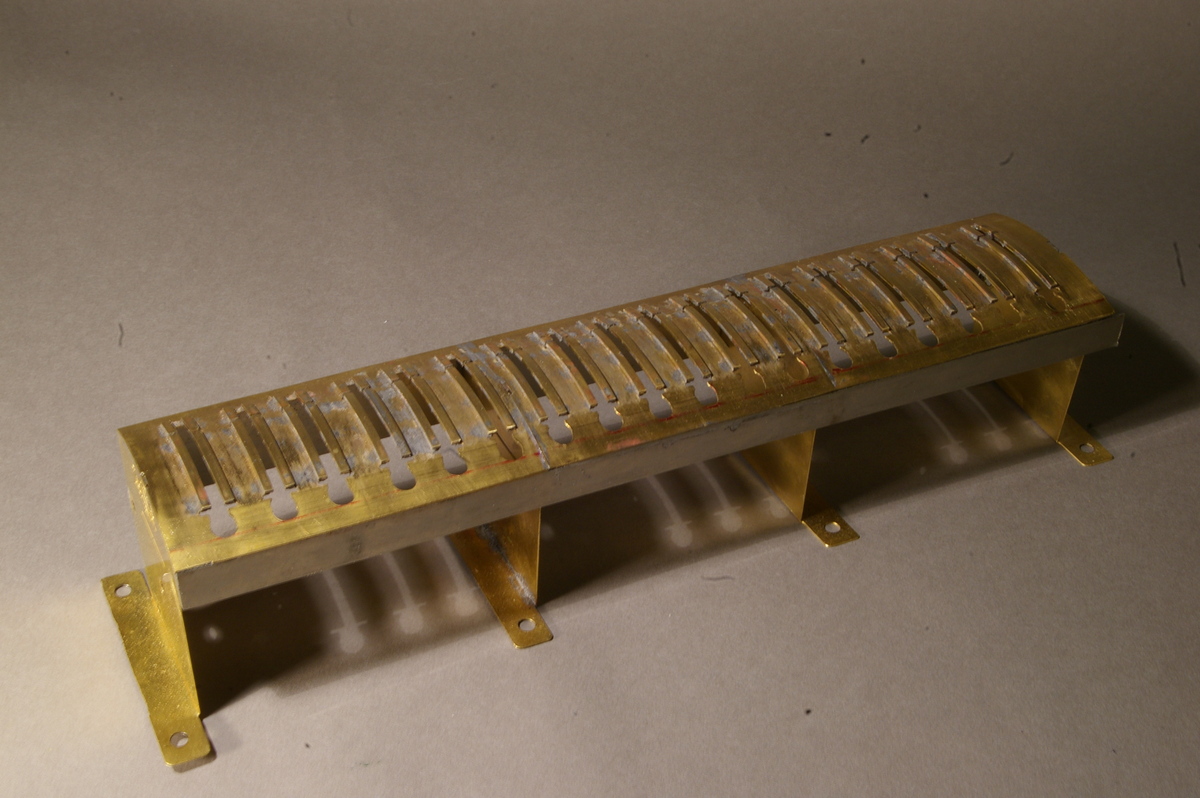
 I’ve devised a better solution using a stirrup made of 4mm by 0.5mm nickel silver strip folded into a long U shape. An 8 BA bolt in the end of the U provides the attachment to, and the adjustment for the tappets in the locking frame. A few hours work, and I’ve made and fitted the 32 new stirrups -
 a great improvement on the brass wire.
The ground frame lever frame is coming together very slowly. It really isn’t very good. The cast levers are perhaps the best available (rather than sweated together etched components) but the geometry of the frame is simply wrong, and the design is such that it will be very difficult to assemble. The design of the catchboxes is very poor – I’ll throw these away and scratchbuild something better.
My photos from Lens have arrived. I have some of them already, but these prints are large and good quality, so more detail shows. I have a second view of the station from the west, which shows a bit more detail of the missing building on the down platform. I’ve concluded that this is the original station building from when the line was opened. (This assumption was later proved incorrect -
December 2012. Trackwork on all four boards is now almost complete apart from the last few switch rails and check rails. We need to check that all the functional chairs are properly glued down.
Once the trackwork is finished we need to think about tie-
 I’ve finally got the ground frame lever frame to first base -
Another walk with a camera and a tape measure, and I have the dimensions of the main station building. A few more days and I have a drawing and then the walls of the building cut-
January 2013. Trackwork is now all in place, and we now have the task of grinding down the rivets so that the cosmetic chairs can be glued in place. This is not my favourite task, but we have at least minimised the effort required by maximising the use of functional chairs. With two of us working together we’ve managed to add the cosmetic chairs to two of the boards – so about 50% complete in a month.
 I’ve more or less finished the carcass of the lever frame for the main box (18 levers) by cutting and joining the 14 lever and 7 lever MSE frames, and adding a few scratchbuilt
 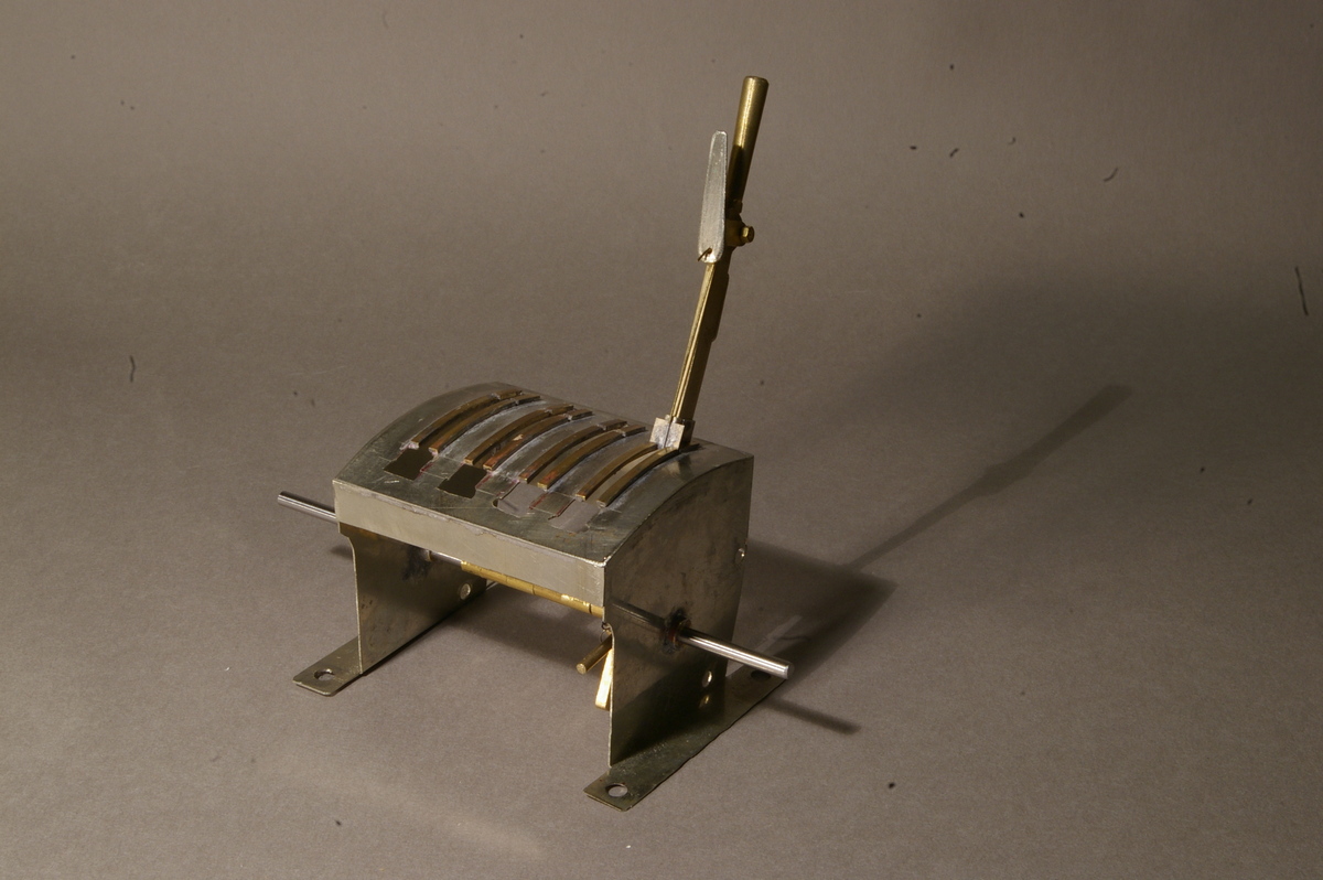 elements (quite a lot actually). I’ve also decided to build a small 4 lever frame for the locally operated points, mimicking the main lever frames, but without interlocking. The main outstanding bit is to redesign the catchboxes, and work out the final assembly.
I’ve sorted out the lifting tappets and sequential locking for the running signals which is all that’s stopped me making the signal box locking frame. Perhaps unnecessary, but I’ve included all the running signals in both directions (home, platform starter, advanced starter as well as distant) in the lever and locking frames, even though only three of these eight signals will be on the scenic section. The off-
 A few day’s work and the main box locking frame is complete and functional together with the locking bars between the two frames.
All I have to do now is sort out the design for the catchboxes, and finish building the lever frames.
February 2013. We were aiming to complete the addition of the cosmetic chairs this month, and we’re almost there. Three and a half boards have been completed, and there’s not much more to do on the last board.
 Maintaining gauge along the length of the turnout switch blades can be a bit of a problem so I’ve decided to use some of Bill Bedford’s brass slide chairs. We’ll use one either side of the tie bar (to avoid melting the plastic slide chairs when the tie bars are soldered in place), together with another one or two along the length of the switch rail. All the others will be C&L plastic slide chairs. The photo shows the brass and plastic slide chairs.
I’ve finally sorted out the catchbox design for the lever frame, so I think I’m on the home run with the lever frames. Both the locking frames have been fitted into their final positions, and I’ve attached the signal box lever frame, and satisfied myself that everything will work when I finally assemble the whole lot.
However, having assembled the signal box lever frame with its locking frame, I’ve come to the conclusion that the drive mechanism connecting the levers to the tappets (using 1mm diameter wire) is not positive enough -
 I’ve devised a better solution using a stirrup made of 4mm by 0.5mm nickel silver strip folded into a long U shape. An 8 BA bolt in the end of the U provides the attachment to, and the adjustment for the tappets in the locking frame. A few hours work, and I’ve made and fitted the 32 new stirrups -