


July 2012. Templot is both brilliant, and frustrating in equal measure, especially if you’re used to ordinary CAD software. It takes a while to get used to the way in which the software generates track templates based on defined parameters, which can then be edited and saved. Creating a series of templates, and joining them together creates the final track plan. The best advice I got when I started, was to understand how ‘pegs’ and ‘notches’ work (they are the means by which adjacent templates can be seamlessly joined together). Excellent advice which got me up and running.
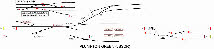
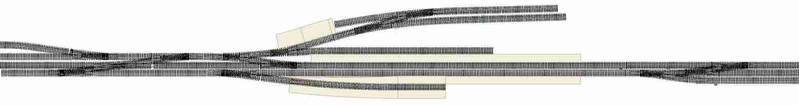
After a few days’ work I have managed to recreate the trackwork for Plumpton at true scale 4mm:1ft, but it is clearly too long. So what can be done? The most obvious change is to model only the crossovers into the lay-bys, with most of the length of the lay-by off-scene. This would make the layout a little over 20ft, which begins to look promisingly like 16ft. By shortening the platforms and the goods yard, and moving the eastern up/down crossover inward the layout can  be shortened a bit further. The goods yard entry (shown on the right) cannot be shortened without tightening the turnouts from B7 to B6, which I’m not prepared to risk in P4. A few further tweaks (making the level crossing slightly less acute for example) and on version 12 of my Templot track plan, I think I have just about achieved a solution – 16ft by 2ft scenic section, with four equal length baseboards, and pointwork which fits neatly relative to the base-
board joints.
 We’ve decided to use interlaced sleepering for the turnouts which was a feature of the Brighton, although the photos I have of Plumpton don’t give a clear indication of whether it was used here or not, apart from one turnout in the goods yard. Learning how to move sleepers around, and create new ones in Templot has been a bit time consuming, but Templot is very flexible and once you get the hang of it, it’s quite straightforward, if a little long-
winded. Also the Brighton typically used short check rails of four sleepers rather than five – something else Templot can happily cope with.
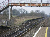 Plumpton has a rather curious dis-
used third platform on the up side (the race-course side), which is separate from the normal platform (there is an ugly Southern Railways era footbridge which crosses the line between the two platforms, and which replaced a public footpath board crossing). There is no equivalent platform on the down-side, and I can’t see how this platform could have been used for passenger traffic. I wonder therefore whether this extra platform was used to load and unload horses for the race-course, to keep them separate from passenger traffic? This platform didn’t exist in LBSCR days, but I think the addition of an up-bay for horseboxes would add a bit of operational interest, and is certainly feasible within the space on the base-boards.
A few miles west of Plumpton, close to Keymer junction is the Keymer Brick and Tile works, which had its own standard gauge railway, and also a connection to the main line. With a bit of modeller’s licence, brick making in Plumpton could conceivably have grown in size and stature to become ‘Plumpton Brick and Tile Works’, needing a connection to the main line…………
 With these two additions I think we now have a final track plan (left), with the additional up bay (bottom of the drawing) and the siding to the brickworks leading onto the headshunt at the far left.
The idea for this layout is to make as much as possible (track, buildings, signals etc) before starting on the baseboards. We’re hoping that this will make the final assembly of the layout seem fairly quick, but we shall see.
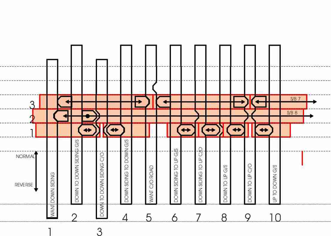
I’ve had some fantastic help from Howard Bolton on the subject of interlocking, including the ins and outs of such seemingly obscure (but essential) topics as lifting tappets and sequential locking and I think I’m now getting somewhere with the locking table (ie what locks or releases what).
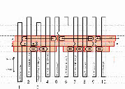 I’ve also had a number of attempts at drawing the design of the locking table. I’ve used CAD software (CorelDraw) to draw out the design at full (model) size, and I’ve done it in such a way that I can move elements of the frame (the tappets and locking bars) and create a sequence of snapshots to demonstrate that my design implements the requirements of the locking table. It’s a bit laborious, but has been worth it I think.
At last we have had a few days of reasonable sunshine for me to take a few photos of the remaining station buildings.
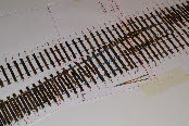
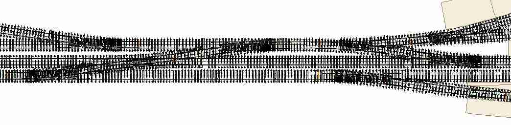
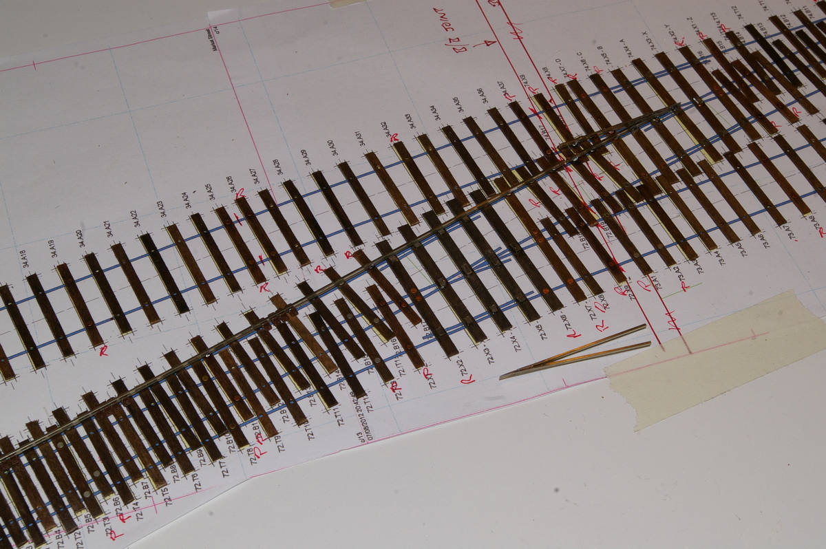
August 2012. A couple of further amendments to the track plan (now version 16) and I think it’s time to start building track. To make the track we’ll be using fairly conventional Scalefour techniques – ply sleepers riveted to enable the rail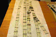 to be soldered to it, followed by the application of cosmetic plastic chairs to hide the rivets. However, rather than riveting every sleeper (and having to apply cosmetic chairs throughout) we will be riveting only every fourth or fifth sleeper on straight track with plastic chairs as functional chairs for the vast majority. For turnouts we will use riveted sleepers under the crossing, and every third or fourth sleeper under the closure rails, as shown in the photo, left.
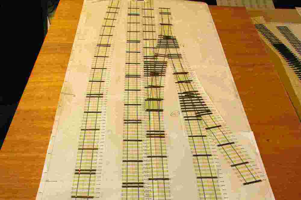
We have enough stained sleepers and rivets from previous layouts, and a few lengths of rail and plastic chairs, so having printed out the track diagram from Templot we can start work!
 After just four weeks, with two of us working together, a lot of progress has been made on the trackwork – two boards have sleepers in position, and we’ve started fixing down the rails, including work on a couple of turnouts in the goods yards.
When making track for Pulborough and Brighton Road we stuck the sleepers to the drawings with double-sided Sellotape. This sticks very stubbornly, making it difficult to separate paper and trackwork when complete, and consequently damaging the track. For Plumpton we’re using Prittstick, which hopefully will alleviate this problem.
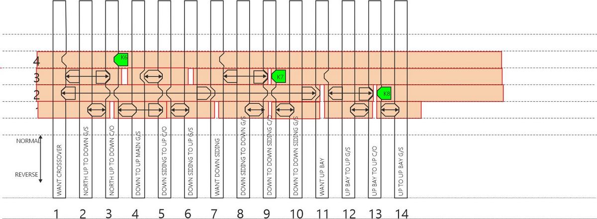
 Having sorted out what I hope is a final design for my locking frame (taking on board the very helpful suggestions from Howard) I have added a further four levers for the up bay. I have also belatedly decided to reverse the numbering on
 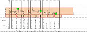 the ground frame levers, because my model lever frame will be facing in the opposite direction (north rather than south), and so that the lever numbers now run sensibly from left to right. However, I’ve had to completely redraw my design………….
After a few days’ work I have managed to recreate the trackwork for Plumpton at true scale 4mm:1ft, but it is clearly too long. So what can be done? The most obvious change is to model only the crossovers into the lay-
 be shortened a bit further. The goods yard entry (shown on the right) cannot be shortened without tightening the turnouts from B7 to B6, which I’m not prepared to risk in P4. A few further tweaks (making the level crossing slightly less acute for example) and on version 12 of my Templot track plan, I think I have just about achieved a solution – 16ft by 2ft scenic section, with four equal length baseboards, and pointwork which fits neatly relative to the base-
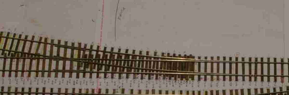 We’ve decided to use interlaced sleepering for the turnouts which was a feature of the Brighton, although the photos I have of Plumpton don’t give a clear indication of whether it was used here or not, apart from one turnout in the goods yard. Learning how to move sleepers around, and create new ones in Templot has been a bit time consuming, but Templot is very flexible and once you get the hang of it, it’s quite straightforward, if a little long-
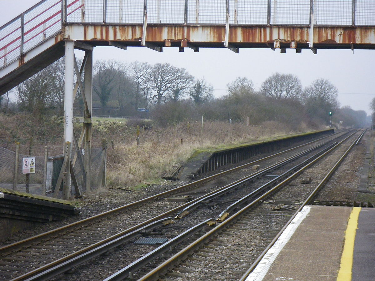 Plumpton has a rather curious dis-
A few miles west of Plumpton, close to Keymer junction is the Keymer Brick and Tile works, which had its own standard gauge railway, and also a connection to the main line. With a bit of modeller’s licence, brick making in Plumpton could conceivably have grown in size and stature to become ‘Plumpton Brick and Tile Works’, needing a connection to the main line…………
 With these two additions I think we now have a final track plan (left), with the additional up bay (bottom of the drawing) and the siding to the brickworks leading onto the headshunt at the far left.
The idea for this layout is to make as much as possible (track, buildings, signals etc) before starting on the baseboards. We’re hoping that this will make the final assembly of the layout seem fairly quick, but we shall see.
I’ve had some fantastic help from Howard Bolton on the subject of interlocking, including the ins and outs of such seemingly obscure (but essential) topics as lifting tappets and sequential locking and I think I’m now getting somewhere with the locking table (ie what locks or releases what).
 I’ve also had a number of attempts at drawing the design of the locking table. I’ve used CAD software (CorelDraw) to draw out the design at full (model) size, and I’ve done it in such a way that I can move elements of the frame (the tappets and locking bars) and create a sequence of snapshots to demonstrate that my design implements the requirements of the locking table. It’s a bit laborious, but has been worth it I think.
At last we have had a few days of reasonable sunshine for me to take a few photos of the remaining station buildings.
August 2012. A couple of further amendments to the track plan (now version 16) and I think it’s time to start building track. To make the track we’ll be using fairly conventional Scalefour techniques – ply sleepers riveted to enable the rail
 to be soldered to it, followed by the application of cosmetic plastic chairs to hide the rivets. However, rather than riveting every sleeper (and having to apply cosmetic chairs throughout) we will be riveting only every fourth or fifth sleeper on straight track with plastic chairs as functional chairs for the vast majority. For turnouts we will use riveted sleepers under the crossing, and every third or fourth sleeper under the closure rails, as shown in the photo, left.
We have enough stained sleepers and rivets from previous layouts, and a few lengths of rail and plastic chairs, so having printed out the track diagram from Templot we can start work!
 After just four weeks, with two of us working together, a lot of progress has been made on the trackwork – two boards have sleepers in position, and we’ve started fixing down the rails, including work on a couple of turnouts in the goods yards.
When making track for Pulborough and Brighton Road we stuck the sleepers to the drawings with double-
 the ground frame levers, because my model lever frame will be facing in the opposite direction (north rather than south), and so that the lever numbers now run sensibly from left to right. However, I’ve had to completely redraw my design………….