

 I’ve also had a number of attempts at drawing the design of the locking table. I’ve used CAD software (CorelDraw) to draw out the design at full (model) size, and I’ve done it in such a way that I can move elements of the frame (the tappets and locking bars) and create a sequence of snapshots to demonstrate that my design implements the requirements of the locking table. It’s a bit laborious, but has been worth it I think.
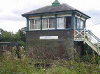
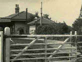
At last we have had a few days of reasonable sunshine for me to take a few photos of the remaining station buildings.
August 2012. A couple of further amendments to the track plan (now version 16) and I think it’s time to start building track. To make the track we’ll be using fairly conventional Scalefour techniques – ply sleepers riveted to enable the rail
 to be soldered to it, followed by the application of cosmetic plastic chairs to hide the rivets. However, rather than riveting every sleeper (and having to apply cosmetic chairs throughout) I will be riveting only every fourth or fifth sleeper on straight track with plastic chairs as functional chairs for the vast majority. For turnouts I will use riveted sleepers under the crossing, and every third or fourth sleeper under the closure rails.
I have enough stained sleepers and rivets from previous layouts, and a few lengths of rail and plastic chairs, so having printed out the track diagram from Templot we can start work!
 After just four weeks, a lot of progress has been made on the trackwork – two boards have sleepers in position, and we’ve started fixing down the rails, including work on a couple of turnouts in the goods yards.
 Having sorted out what I hope is a final design for my locking frame (taking on board the very helpful suggestions from Howard) I have belatedly decided to reverse the numbering on
  the ground frame levers, because my model lever frame will be facing in the opposite direction (north rather than south), and so that the lever numbers now run sensibly from left to right. However, I’ve got to completely redraw my design………….
September 2012. Lots more activity on the trackwork. Most of the sleepers are now in place on the four boards, and Chris has made lots of progress on soldering the rails in place.
 Another walk to the station and I have been able to photograph the signal box, up waiting room and footbridge. I have also taken the basic measurements of the waiting room, and
  prepared a drawing. I think it’s well-
As part of the local Jubilee celebrations one of our local historians has published a little booklet of historic postcards of Plumpton, including a couple of very interesting views from around 1910, giving just slightly better views of the
 station, and the two mysterious buildings which no longer exist. One of them looks very much like a signal box, and could have been the original box prior to the current (1891) box – but why is it still there in 1910 – and even in early Southern days? The other building is just tantalisingly out of view. Most of the shots are taken from the level crossing end (east end) of the station. A view from the western end would be invaluable.
 I’m a fairly frequent visitor to our village hall, and there are about a dozen historic pictures of Plumpton in the entrance hallway. I’ve looked at these a few times, but clearly hadn’t been paying attention. Another visit last night, and a casual look at the pictures – and there it is – a shot from the west end of the station. This shows reasonably clearly that the missing building at the west end is in fact a close but not identical version of the up (still existing) waiting room.
 The size of the building is confirmed by the footprint on the plans I have. I can’t quite see enough to confirm the positions pf the windows and doors, but enough to make an intelligent guess.
At Scaleforum I made contact with Lens of Sutton, and their catalogue shows 14 pictures of Plumpton, although none dated. The only answer is order the lot – a few weeks to wait to see what they show.
I’ve now got most of the components to make the locking frames. The main box will have 18 levers, and the ground frame 14. The main box has three levers which release point locks (ie physically prevent the blades from moving) on the cross-
I already have one of the MSE 14 lever frames, and although I have been advised against using these (they are badly designed and drawn) I feel I can’t simply throw away this investment and start again. The downside is that I have to buy another 14 lever frame, plus a 7 lever frame. Will I regret this? I also need to decide how to operate the four locally operated turnouts in the yard which are not interlocked with anything.