


Updated January 2026
Stroudley C class 0-6-0 no 405 goods tender engine
Stroudley C1 class 0-6-0 no 427 goods tender engine
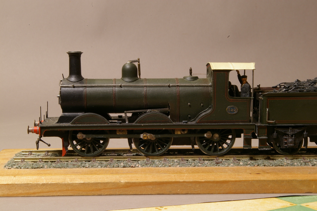
Billinton C2 class 0-6-0 no 522 goods tender engine
Marsh C3 class 0-6-0 no 309 goods tender engine
 The first batch of 12 C2’s were ordered in 1891, shortly after R J Billinton took over from William Stroudley, with delivery in 1893, immediately followed by a second order of a further 8 in 1894. A significant increase in goods traffic in 1898 prompted a third order, for 15 engines which included no 522, and two subsequent batches of 5 and 15, bringing the total number to 55. The C2’s proved able to steam more freely than their Stroudley predecessors, making them useful as occasional passenger engines, but not as powerful. Many were subsequently reboilered using the C3 boiler which resulted in powerful heavy-
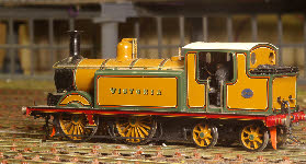
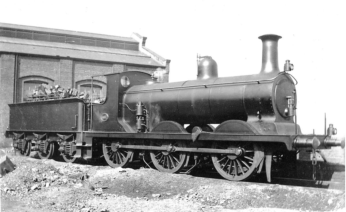
duty goods engine capable of handling the most arduous main-line goods duties. The photo on the left shows no 531 in Stroudley goods green.
 When this loco first appeared from the dark recesses of my work-
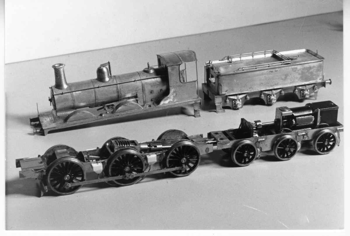
bench, sometime around 1987, it was fitted with a tender drive, via two universal joints to the engine chassis. My main reason for doing this was to maximise the space available in the engine itself for filling with lead, to make sure there was plenty of traction available.
This worked well and the engine has run successfully for many years, but unfortunately was known as 'the coffee-grinder' because of the noise of the spur gears in the tender. Without the tender body the loco was reasonably quiet, but adding the body seemed to amplify the noise. My attempts at deadening the sound were a complete failure.
In 2007, after 20 years in service, I decided that a major refit was the only solution, and the pictures below show the new chassis.
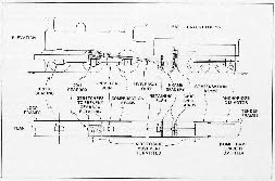
 This was the original layout, as shown in my articles for MRJ nos 19 and 20. The spur gears are mounted on a paxolin base, and there are two universal joints, one between the tender and engine, and the other immediately aft of the worm and wheel gearbox.
 The tender has split axle pick-
up. There are no pick-ups on the engine chassis. The drawing below shows the original layout.
 The engine chassis has been reconstructed as split-
frame, with my usual copper-clad paxolin frame spacers, to insulate the side frames. The wheels have 6thou phosphor-bronze wire soldered to the tyres at one end, and poked into the axle hole at the other. When the axle is pushed into the axle hole in the wheel this holds the wires in place, and provides the connection from the tyre to the axle.
Photographs of this can be seen here.
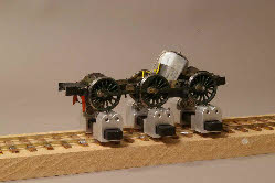
This photo also shows my latest acquisition - a 'Bachrus' rolling road. Not cheap, but definitely a worthwhile investment. I bought four sets (three shown here). The concept is very simple. All you need is a length of straight track, adjust the gauge of the rolling road to the track, and position them under the wheels. These rollers will fit any gauge from 11mm to 23mm (TT to S gauge).
Current is picked up from the rails, so no further connections to the loco are required.
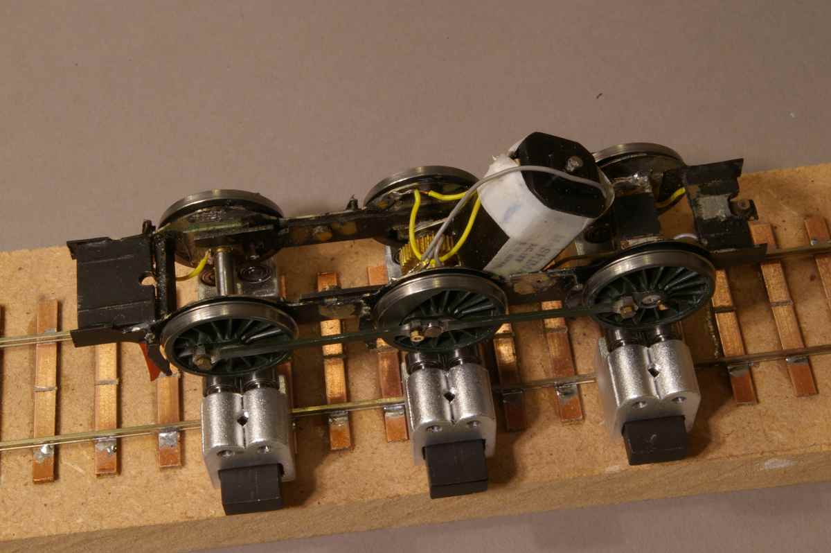
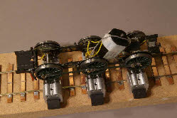 Another view, showing a bit more detail. I've had to reverse the compensation on the loco chassis, by putting the side beams at the front, to give enough width to fit the motor between the frames, in the fire box. The motor is a small Mashima can, with a Branchlines gearbox.
Stroudley C class 0-
Stroudley C1 class 0-
Billinton C2 class 0-
 The first batch of 12 C2’s were ordered in 1891, shortly after R J Billinton took over from William Stroudley, with delivery in 1893, immediately followed by a second order of a further 8 in 1894. A significant increase in goods traffic in 1898 prompted a third order, for 15 engines which included no 522, and two subsequent batches of 5 and 15, bringing the total number to 55. The C2’s proved able to steam more freely than their Stroudley predecessors, making them useful as occasional passenger engines, but not as powerful. Many were subsequently reboilered using the C3 boiler which resulted in powerful heavy-
 When this loco first appeared from the dark recesses of my work-
This worked well and the engine has run successfully for many years, but unfortunately was known as 'the coffee-
In 2007, after 20 years in service, I decided that a major refit was the only solution, and the pictures below show the new chassis.
 This was the original layout, as shown in my articles for MRJ nos 19 and 20. The spur gears are mounted on a paxolin base, and there are two universal joints, one between the tender and engine, and the other immediately aft of the worm and wheel gearbox.
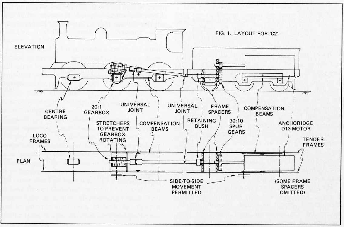 The tender has split axle pick-
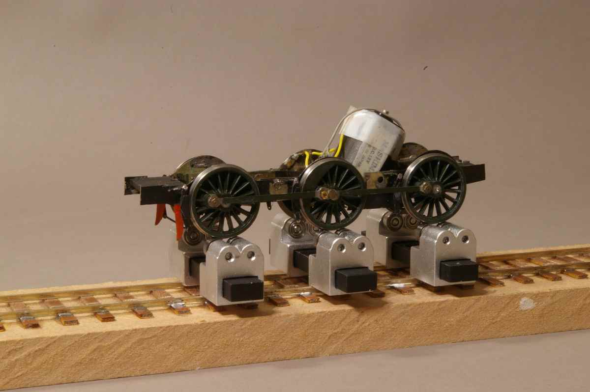 The engine chassis has been reconstructed as split-
Photographs of this can be seen here.
This photo also shows my latest acquisition -
Current is picked up from the rails, so no further connections to the loco are required.
 Another view, showing a bit more detail. I've had to reverse the compensation on the loco chassis, by putting the side beams at the front, to give enough width to fit the motor between the frames, in the fire box. The motor is a small Mashima can, with a Branchlines gearbox.
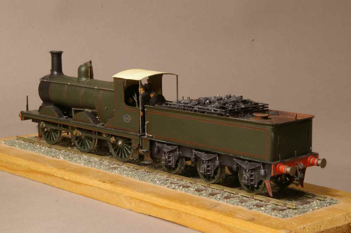 A three-
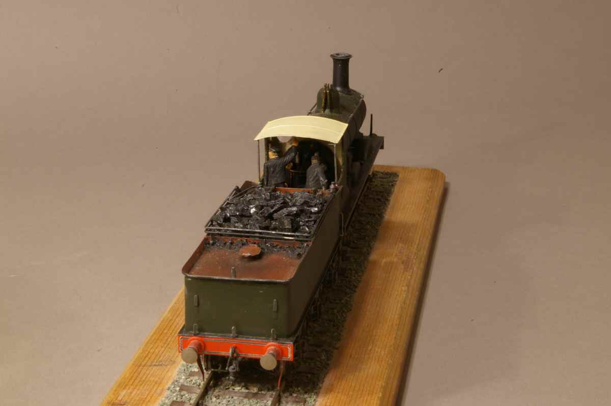
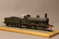
 Photographs can be very cruel, but are also a useful way to check detail. I have now straightened out the bent lamp iron in front of the chimney, and the safety valve springs! I still have to adjust the relative heights of the loco and tender.
I’ve had a few problems with this engine derailing when running in reverse, and I diagnosed it as too little weight on the trailing axle -
As part of my experiments checking axle loadings and load haulage capabilities, the engine has now had a bit of a spruce up -