


Added January 2017
I2 No 13
I3 No 22
 The story of Marsh’s Atlantic tanks is not a happy one. Marsh’s dislike of large-
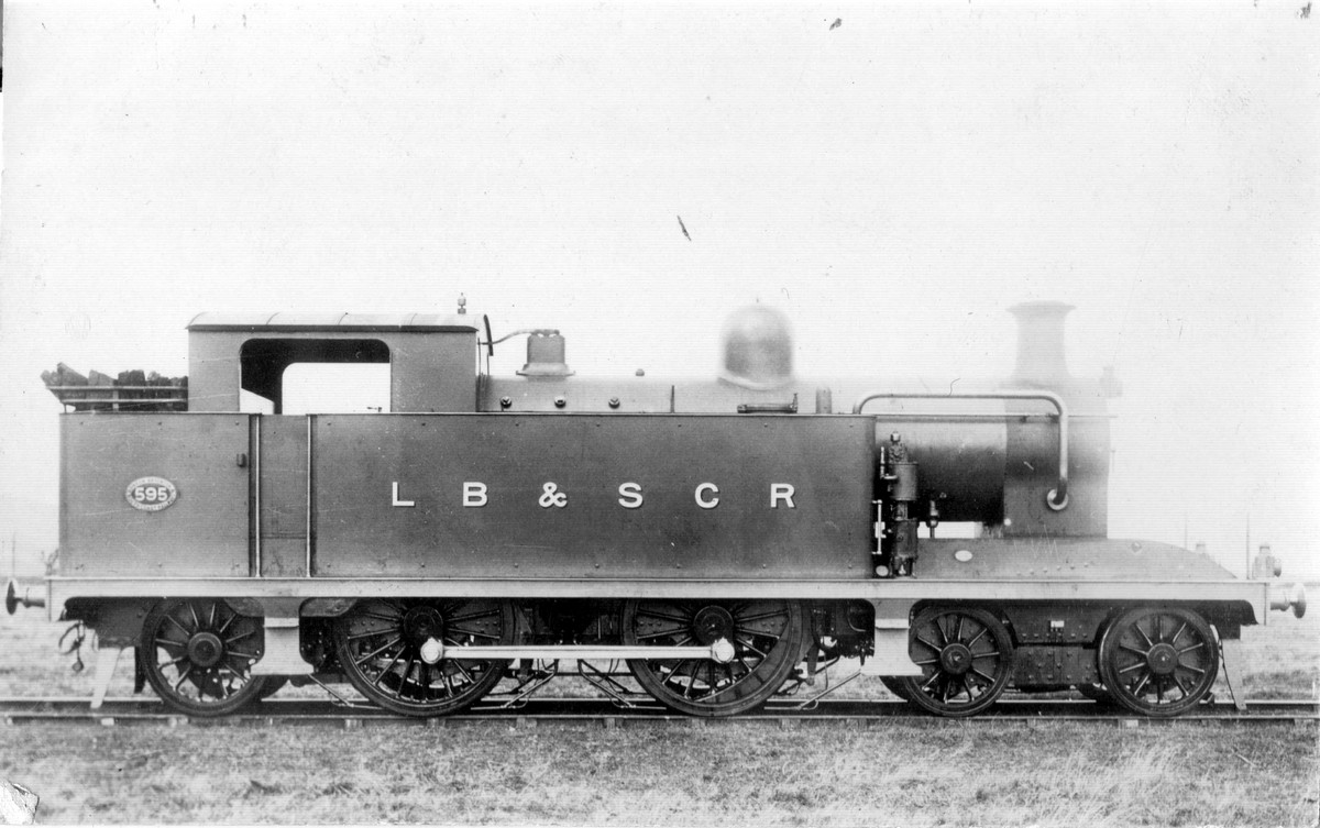
wheeled front coupled loco’s led him first to experiment with the removal of the leading coupling rods from twenty E4 and E5 0-6-2 tanks, and then subsequently to produce a new design of 4-4-2 tanks in 1905. The first of these types, the I1’s (photo right), were a complete failure, the principal reason being poor draughting, and an undersized grate. It was intended that 30 would be built, but the last ten were cancelled, perhaps prompted by a poor performance on a Royal special to Epsom for the Derby, with Marsh himself on the footplate.
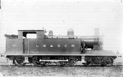
 The design was revisited, resulting in the I2 class, (photo left) which had slightly larger boilers (4’6” compared with 4’3”), and a longer wheelbase. These locos were equally poor, at least in part because the firebox design was identical to the I1’s. At the same time as the I2’s were being built, Marsh was in the process of designing the prototype I3 (which perhaps owes more to the skills of the recently appointed Chief Locomotive Draughtsman, Basil Field than Marsh himself). Curiously the first I3 (no 21) appeared in October 1907, two months before the first of the I2’s. Five of the I2’s should have received superheated boilers, supplied by the North British Locomotive Company, but in the event delivery of these boilers was delayed, and all ten I2’s were turned out with saturated boilers.
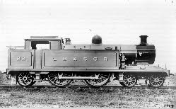
 The superheated boilers were subsequently built into a further five engines of similar design to the I2’s, originally designated as ‘superheated I2’s’ but later reclassified as I4’s (photo right). These engines were equally poor performers, notwithstanding the superheated boilers, again as a result of the inadequate grate size, and poorly design front end.
 The I3 design arose from the availability of a boiler intended as one of five spares for the B4 4-
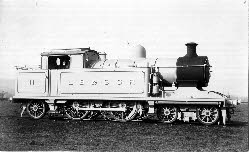
4-0 tender engines. The I3 design thus incorporated many successful features of the B4’s - 6’9” coupled wheels (compared with 5’6” for I1, 2 and 4’s), cylinders and motion, and firebox. The first of the I3’s (no 21) was put to use on the London expresses, where it performed well alongside the H1 Atlantic tender engines, although with excessive coal consumption. This seems to have led to Marsh and Field incorporating superheating in no 22, the second of the class (together with a reduction of the wheel diameter to 6’7½”). A further four superheated I3’s were built, followed by six with saturated boilers. A further 15 (all superheated) were built in the period up to 1913.
The most spectacular demonstration of the outstanding performance of the I3’s was their performance during trials running the ‘Sunny South Express’ from Brighton to Rugby. The I3’s easily outstripped the LNWR ‘Precursor’ in terms of time-keeping, and coal and water usage.
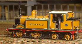
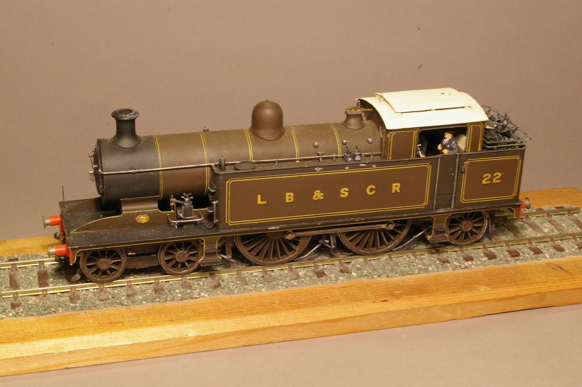
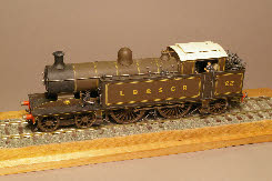 I have chosen to build no 22, principally because of its interest as the first superheated engine on the Brighton, and its performance in the Sunny South Express trials. The body is entirely scratchbuilt in nickel-
silver, with turned brass fittings, and based on the weight diagram and photographs.
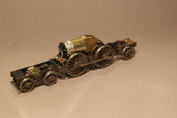 The chassis, in common with my other scratchbuilt efforts is fully compensated, with split axle pickup (on drivers and trailing radial axle), and it uses a large Portescap motor/gearbox which had been given to me. Compensating a five axle loco is slightly complex. I have used side beams between the rear driven axle and the radial axle box, with a central beam between the front drivers and the leading bogie.

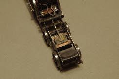 The bogie frames can rotate, and move up and down, whilst the two axles can move independently, supported by a central beam, as shown in the photo left. The bogie can also move from side-
to side with centring provided by the compensation beam (shown in the photo right). This particular feature was incorporated to ensure adequate horizontal flexibility to enable the loco to traverse tight-ish curves. However, it has proved to be an unnecessary complication, and I won’t repeat it again when (if) I get around building an I2 or H. My other bogie engines (B4 and D3) are equipped with a simple pivot for the bogie, and these quite happily negotiate B6 turnouts.
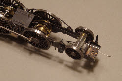 The photo left shows the radial axle box with a spring to centralise the box on straight track. This is feature which I added because of the relatively short wheel base, the front bogie with sideplay, and my concerns about ensuring that the loco runs true on straight track. It seems superfluous in hindsight, and I have not used on other locos with radial boxes. A simpler solution would have been a front bogie with a simple pivot (no side-
to-side movement), which would have ensured straight running, and a radial box without any centralising spring.

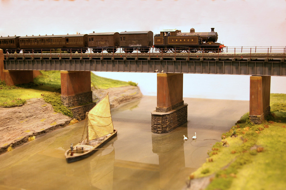
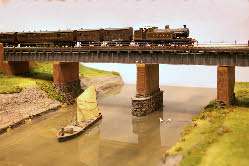 These two photos show (left) no 22 on the Arun bridge on our layout ‘Pulborough’, and (right) on the high-
level section on ‘Brighton Road’.
I2 No 13
I3 No 22
 The story of Marsh’s Atlantic tanks is not a happy one. Marsh’s dislike of large-
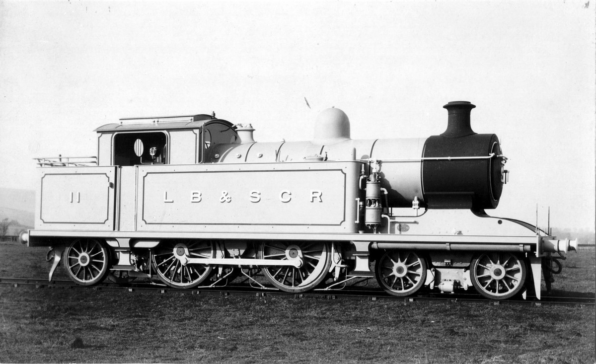 The design was revisited, resulting in the I2 class, (photo left) which had slightly larger boilers (4’6” compared with 4’3”), and a longer wheelbase. These locos were equally poor, at least in part because the firebox design was identical to the I1’s. At the same time as the I2’s were being built, Marsh was in the process of designing the prototype I3 (which perhaps owes more to the skills of the recently appointed Chief Locomotive Draughtsman, Basil Field than Marsh himself). Curiously the first I3 (no 21) appeared in October 1907, two months before the first of the I2’s. Five of the I2’s should have received superheated boilers, supplied by the North British Locomotive Company, but in the event delivery of these boilers was delayed, and all ten I2’s were turned out with saturated boilers.
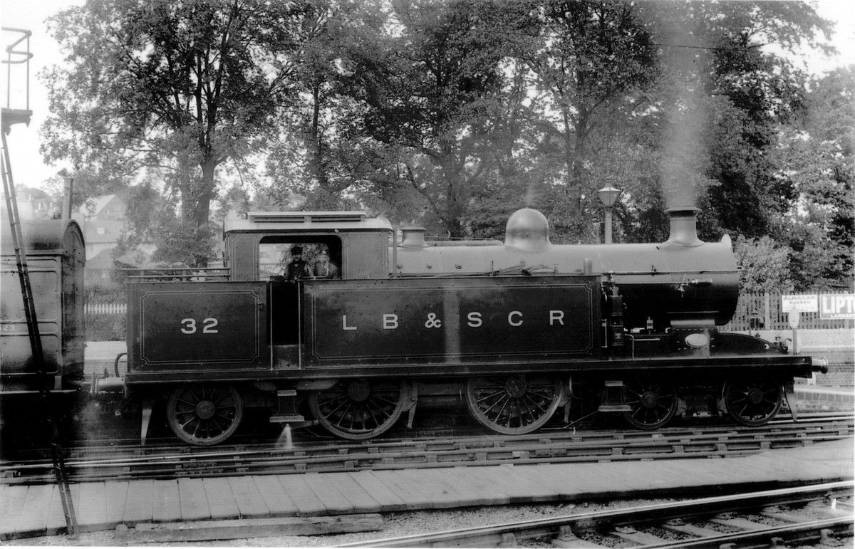 The superheated boilers were subsequently built into a further five engines of similar design to the I2’s, originally designated as ‘superheated I2’s’ but later reclassified as I4’s (photo right). These engines were equally poor performers, notwithstanding the superheated boilers, again as a result of the inadequate grate size, and poorly design front end.
 The I3 design arose from the availability of a boiler intended as one of five spares for the B4 4-
The most spectacular demonstration of the outstanding performance of the I3’s was their performance during trials running the ‘Sunny South Express’ from Brighton to Rugby. The I3’s easily outstripped the LNWR ‘Precursor’ in terms of time-
 I have chosen to build no 22, principally because of its interest as the first superheated engine on the Brighton, and its performance in the Sunny South Express trials. The body is entirely scratchbuilt in nickel-
 The chassis, in common with my other scratchbuilt efforts is fully compensated, with split axle pickup (on drivers and trailing radial axle), and it uses a large Portescap motor/gearbox which had been given to me. Compensating a five axle loco is slightly complex. I have used side beams between the rear driven axle and the radial axle box, with a central beam between the front drivers and the leading bogie.
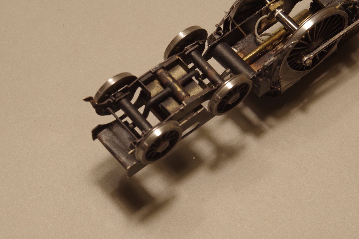
 The bogie frames can rotate, and move up and down, whilst the two axles can move independently, supported by a central beam, as shown in the photo left. The bogie can also move from side-
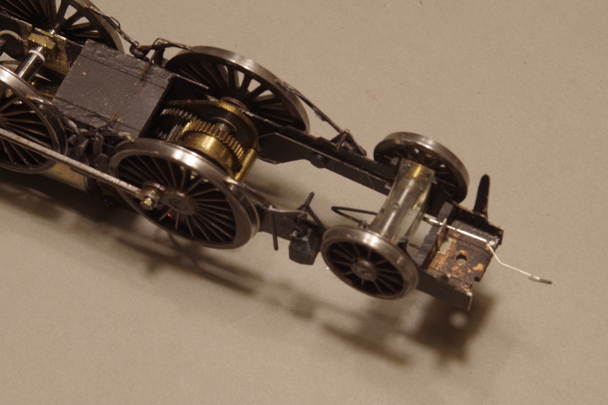 The photo left shows the radial axle box with a spring to centralise the box on straight track. This is feature which I added because of the relatively short wheel base, the front bogie with sideplay, and my concerns about ensuring that the loco runs true on straight track. It seems superfluous in hindsight, and I have not used on other locos with radial boxes. A simpler solution would have been a front bogie with a simple pivot (no side-
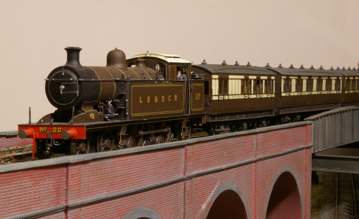
 These two photos show (left) no 22 on the Arun bridge on our layout ‘Pulborough’, and (right) on the high-