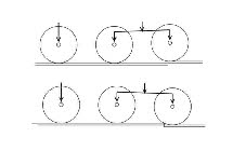


Figure 1b
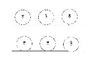
Figure 1a
DESIGN CONCEPTS
There are many details to think about when designing a chassis, but the main principles I think are horizontal and vertical flexibility, weight distribution (especially for smaller prototypes), electrical pick-up and motor mounting.
 Vertical flexibility can be achieved through a variety of sprung methods, or compensation -
 my personal preference. With the real thing, the springs are carefully designed to balance the weight of the loco, and to provide appropriate spread of axle loads. This is all but impossible to achieve in small scale models. If the springs are made stiff enough to accommodate the weight of the loco, they will probably be too stiff to accommodate much downward movement, and hence be able to apply any load to the axle if there is a dip in the track. The individual axle loads will therefore vary over any possible variation in track level. Figure 1a illustrates what happens.
My personal preference has always been for compensation, using the methods first outlined by Mike Sharman - it’s simple and proven technology. Having said that, the quietest loco I ever built was a sprung Terrier, using the nylon Maygib hornblocks - at least, it worked well until the nylon disintegrated after a couple of years. I’m also aware of the new ‘continuous sprung beam’ method, and I can see that this could be a useful addition to the armoury, especially for six-coupled locos where weight distribution is less of an issue, or the addition of leading and trailing bogies adds to the complexity of compensation systems.
The most complex chassis I have built is an I3 (4-4-2) which is fully compensated, with weight bearing leading bogie and trailing radial axle box.
 Figure 1b illustrates my point about consistent axle loading when the track may not be particularly level. Regardless of the vertical positions of the axles, the weight distribution will remain unchanged. Perfectly level trackwork is obviously desirable, but not always achievable I think, especially across base board joints on an exhibition layout.
There are many details to think about when designing a chassis, but the main principles I think are horizontal and vertical flexibility, weight distribution (especially for smaller prototypes), electrical pick-
 Vertical flexibility can be achieved through a variety of sprung methods, or compensation -
My personal preference has always been for compensation, using the methods first outlined by Mike Sharman -
The most complex chassis I have built is an I3 (4-
 Figure 1b illustrates my point about consistent axle loading when the track may not be particularly level. Regardless of the vertical positions of the axles, the weight distribution will remain unchanged. Perfectly level trackwork is obviously desirable, but not always achievable I think, especially across base board joints on an exhibition layout.