

Updated March 2021
This is re-run of an article I wrote in 2016 for ‘Modeller’s Digest’, produced by the Brighton Circle.
I started work on the signal box for Plumpton Green almost four years ago, and it’s been almost finished for two years – lacking just the brackets under the eaves, and the finial/ventilator on the roof. The brackets were my first attempt at 3D printing, and arrived from the printer (ModelU) in early September – but not without a few difficulties on my part in producing the original drawing.
This is re-
I started work on the signal box for Plumpton Green almost four years ago, and it’s been almost finished for two years – lacking just the brackets under the eaves, and the finial/ventilator on the roof. The brackets were my first attempt at 3D printing, and arrived from the printer (ModelU) in early September – but not without a few difficulties on my part in producing the original drawing.
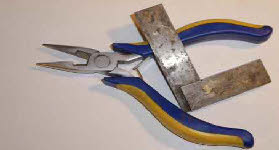
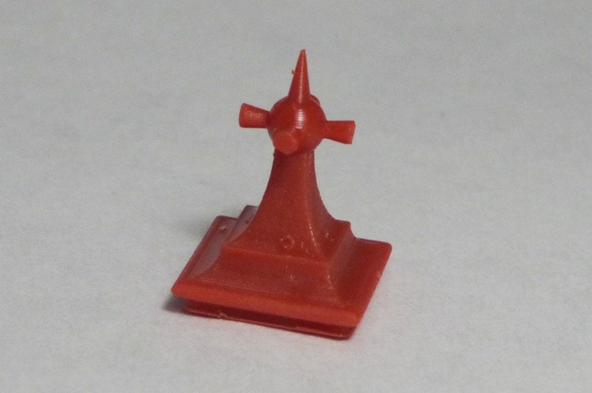
 The finial on the roof of the signal box is a very complex shape, as shown in the adjacent photograph, and a few attempts at scratchbuilding it demonstrated the difficulty of replicating at 4mm:ft. However, my minor success with the brackets spurred me on to get the finial sorted out. In my search for better software capable of drawing 3D solids (as opposed to 3D mesh objects) I stumbled across AutoDesk123D. This is a free program, and is simple enough to get to grips with, within a few hours. However, its simplicity doesn’t mean you can’t make complex shapes given a little forethought and ingenuity. Regrettably 123D is no longer available (March 21), but a good alternative seems to be TinkerCAD.
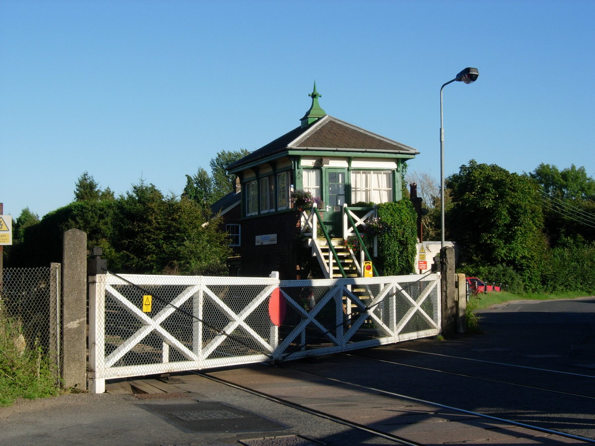
 The photographs illustrate firstly, the finished finial, with the second photo showing an exploded view of the ten component parts. The program allows you to create ‘primitives’ (simple cuboid, cylinder, cone, sphere, toroid) defined only by their dimensions. These primitives can then be combined in various ways (merge, subtract, intersect, separate) to create more complex shapes.
#
 In the exploded view, the bottom layer is a simple cuboid, whilst the second is also a cuboid, but with externally radiused edges (‘fillets’ in the language of the program).
 The third and fourth layers are a little more complex, and the construction of the fourth layer is shown in the next five photos. The starting point is a cuboid and a cylinder. By aligning the cylinder with the edge of the cuboid, and subtracting the cylinder, a concave face is created, which can be repeated on the other three side faces. The final stage is to stretch the object upwards to its finished height.
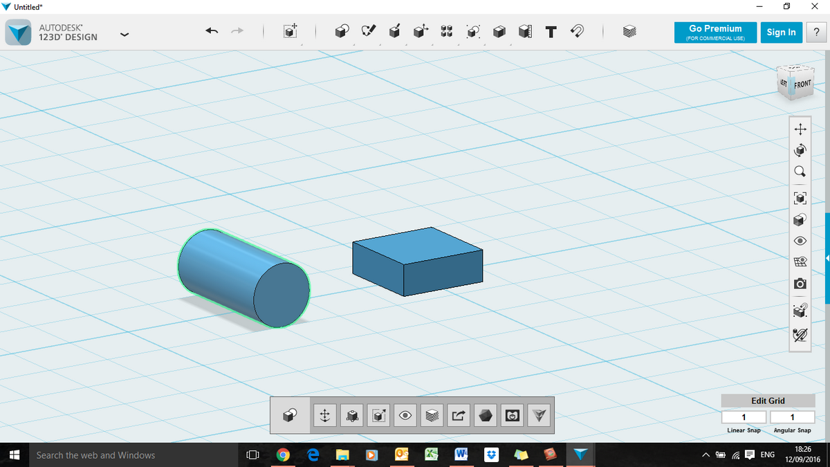
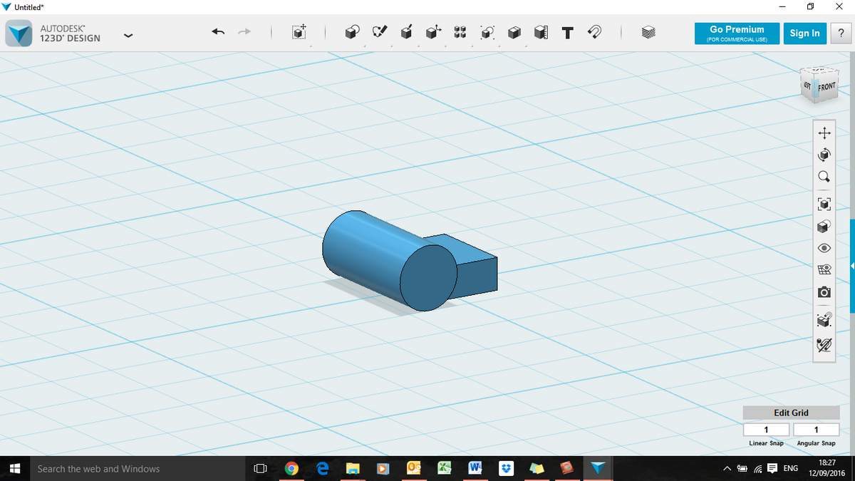

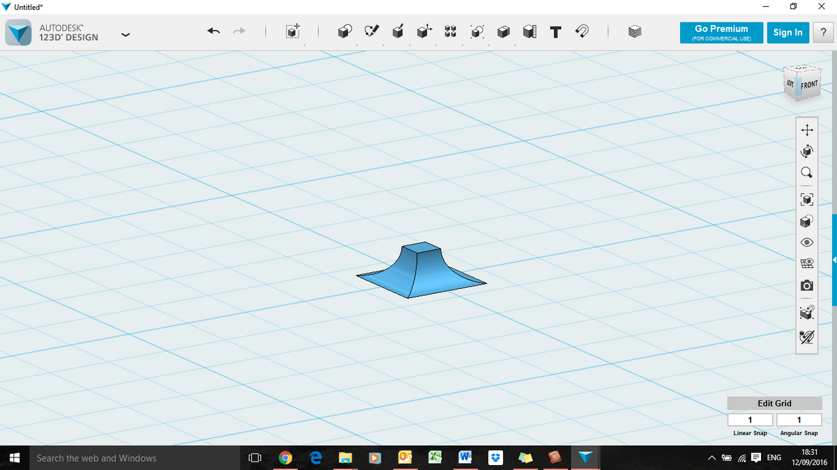
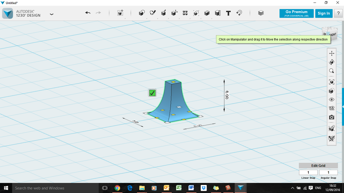
The only complication is working out the starting dimensions of the cuboid and the cylinder. To remove a perfect quadrant from the edge of the cuboid, the cylinder radius must be the same height as the cuboid. The dimensions of the top face are also dependent on the radius of the cylinder – the length and breadth of the top face will be the length and breadth of the bottom face less twice the radius of the cylinder.
For my finial the bottom face of the fourth component needs to be 6.8 X 6.8mm, and the top face 2 X 2mm. The radius of the cylinder must be half the difference between these two measurements = (6.8-2)/2 = 2.4mm. The height of the cuboid must be the same as the radius of the cylinder to start with (2.4mm). Once the concave sides have been formed it can be stretched upwards to the finished height (6.5mm).
The top six pieces are all ‘primitives’ – a sphere and five cones.

 The final stage is to move the components around to build the finished object. AutoDesk123D is a bit clunky in this respect because it doesn’t use an absolute co-