

To make transporting the layout a bit easier I need the baseboards to be all the same size (4ft by 2ft), and I’ve been able to arrange the trackwork such that none of the turnouts crosses any of the baseboard joints. We’re building all the track before starting on the baseboards, so we’ll be able to ensure that any cross-bracing avoids turnout operating mechanisms.
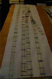
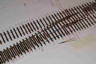
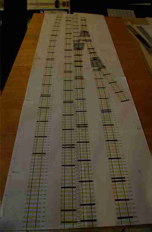
I’ve started by printing out the entire layout at finished size, and stuck the numerous pages together for each of the four boards. Laying these out on the floor gives a real view of the finished layout, but also gives an indication of the daunting task of building a lot of track!
The sleepers we’re using were dyed many years ago using Colron wood dye of various tints, to try to emulate the natural variation in the colouring of real sleepers. I used Colron because it doesn’t smell much, isn’t oily like creosote (which might make gluing plastic chairs difficult) and because of the variety of colours available. I have a ready supply of copper rivets, so the next task is to rivet the plain sleepers, and glue them onto the trackwork printout. Because I’m using interlaced sleepering I don’t have too many crossing timbers to mark out and rivet.
When making track in the past I have used double-sided sellotape to (temporarily) stick the sleepers to the track plan, whilst making the track, and before separating the finished piece of track from its paper plan and final laying. However, sellotape can stick too well, and separating the track from the plan can result in a bit of damage. This time we’ve used just a tiny dab of Pritt-stick under each sleeper, so that when we need to, we will be able to remove the track without damage.
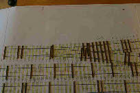 The photo shows the first stage for one of the boards, with all the riveted sleepers (where the rail will be soldered) fixed down with Pritt. The straight track has a riveted sleeper either side of every rail joint, and then typically every fifth sleeper -
 all the rest will use functional chairs.
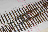
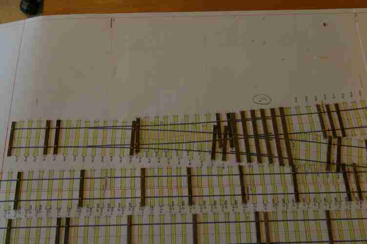
The second photo shows one of the turnouts, showing a bit more detail of which sleepers are riveted.
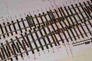
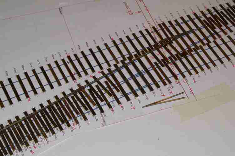
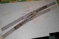 The third photo shows the two yard turnouts, with all sleepers fixed in place, ready to receive the rails. The riveted sleepers can be seen, and the plain sleepers will use functional plastic chairs.
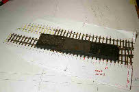
One of the problems I’ve encountered previously when making pointwork is what to do under the crossing V, wing rails and check rails. I think Pulborough used ordinary rivets close together to provide enough area to solder the rail to. Brighton Road used thin copper clad paxolin araldited to the wooden sleepers, but these have suffered from the copper cladding detaching from the paxolin - I think 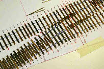 because the surface area is small, and the heat required to solder the rail is enough to detach the copper. For Plumpton I’ve opted for small pieces of nickel-
silver araldited to the sleeper, as shown, left. Provided the araldite is left for 24 hours to harden, it appears to resist the soldering temperature - assuming you’re quick with the soldering iron.
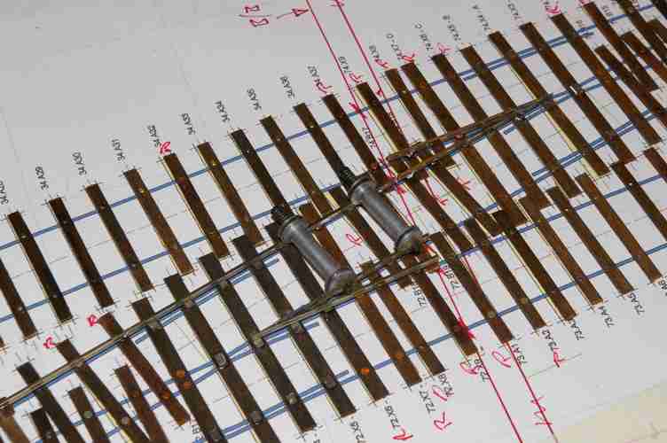
Switch rails and V’s have been made using the tried and tested methods described in the Scalefour Manual, although I have made a jig to help with the assembly of the V’s. I have also cheated a bit, and bought some ready made V’s and switches from a friend, surplus to his requirements. My preference for fitting the rails is to start from the middle of the turnout (the ‘V’) and to then fit the stock rails either side. An alternative would be to fit the straight stock rail, and then the V, followed by the curved stock rail. The photos below show the first ‘V’ for the right-most turnout in place, together with the curved stock rail for the left-most turnout. With these rails in place, the second ‘V’ can be accurately positioned using gauges, and soldered into place (second photo). Once this is done the remaining stock rails and closure rails can be added.
 The functional chairs have been slid onto the rails before soldering the rails to the rivets, and can just about be seen in the photos, in groups of three or four between the riveted sleepers. Once all the soldering has been completed, the chairs can be slid along the rails to their final positions, before being glued to the sleepers.
 In theory, gluing plastic to wood shouldn’t work. However, using a fairly aggressive solvent such as Butanone effectively melts the plastic sufficiently so that the application of weight while the glue dries is enough to create a strong mechanical bond. If there is a need at a later stage to adjust the gauge, then a scalpel blade between chair and sleeper will break the bond so that the gauge can be adjusted, and the chair reglued. (I’d like to say here that my trackwork never needs gauge adjustment after completion, but I’d be lying).
If more strength is required, then a dab of Polypipe cement on the sleeper (and allowed to dry) prior to fixing the chairs with Butanone will make an almost unbreakable bond.
I’ve started by printing out the entire layout at finished size, and stuck the numerous pages together for each of the four boards. Laying these out on the floor gives a real view of the finished layout, but also gives an indication of the daunting task of building a lot of track!
The sleepers we’re using were dyed many years ago using Colron wood dye of various tints, to try to emulate the natural variation in the colouring of real sleepers. I used Colron because it doesn’t smell much, isn’t oily like creosote (which might make gluing plastic chairs difficult) and because of the variety of colours available. I have a ready supply of copper rivets, so the next task is to rivet the plain sleepers, and glue them onto the trackwork printout. Because I’m using interlaced sleepering I don’t have too many crossing timbers to mark out and rivet.
When making track in the past I have used double-
 The photo shows the first stage for one of the boards, with all the riveted sleepers (where the rail will be soldered) fixed down with Pritt. The straight track has a riveted sleeper either side of every rail joint, and then typically every fifth sleeper -
The second photo shows one of the turnouts, showing a bit more detail of which sleepers are riveted.
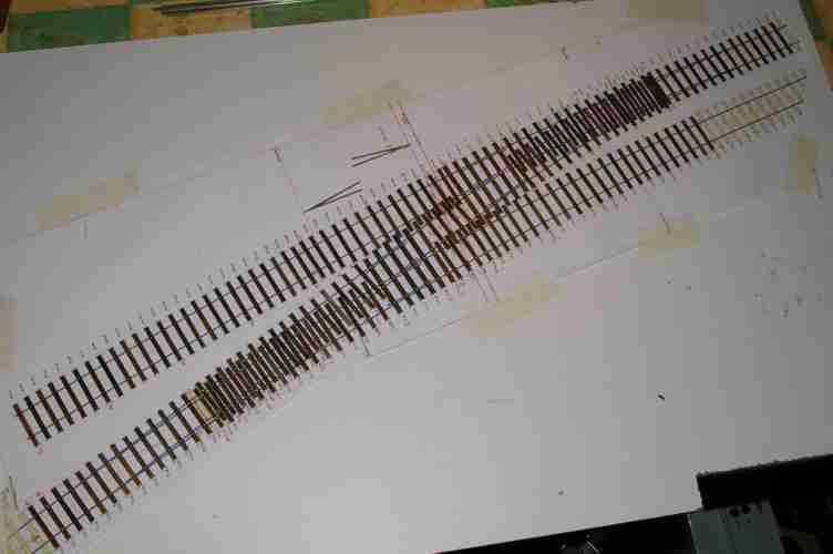 The third photo shows the two yard turnouts, with all sleepers fixed in place, ready to receive the rails. The riveted sleepers can be seen, and the plain sleepers will use functional plastic chairs.
One of the problems I’ve encountered previously when making pointwork is what to do under the crossing V, wing rails and check rails. I think Pulborough used ordinary rivets close together to provide enough area to solder the rail to. Brighton Road used thin copper clad paxolin araldited to the wooden sleepers, but these have suffered from the copper cladding detaching from the paxolin -
 because the surface area is small, and the heat required to solder the rail is enough to detach the copper. For Plumpton I’ve opted for small pieces of nickel-
Switch rails and V’s have been made using the tried and tested methods described in the Scalefour Manual, although I have made a jig to help with the assembly of the V’s. I have also cheated a bit, and bought some ready made V’s and switches from a friend, surplus to his requirements. My preference for fitting the rails is to start from the middle of the turnout (the ‘V’) and to then fit the stock rails either side. An alternative would be to fit the straight stock rail, and then the V, followed by the curved stock rail. The photos below show the first ‘V’ for the right-

 The functional chairs have been slid onto the rails before soldering the rails to the rivets, and can just about be seen in the photos, in groups of three or four between the riveted sleepers. Once all the soldering has been completed, the chairs can be slid along the rails to their final positions, before being glued to the sleepers.
  In theory, gluing plastic to wood shouldn’t work. However, using a fairly aggressive solvent such as Butanone effectively melts the plastic sufficiently so that the application of weight while the glue dries is enough to create a strong mechanical bond. If there is a need at a later stage to adjust the gauge, then a scalpel blade between chair and sleeper will break the bond so that the gauge can be adjusted, and the chair reglued. (I’d like to say here that my trackwork never needs gauge adjustment after completion, but I’d be lying).
If more strength is required, then a dab of Polypipe cement on the sleeper (and allowed to dry) prior to fixing the chairs with Butanone will make an almost unbreakable bond.