

Last updated May 2023
Running signals for Brighton Road
 Brighton Road needed quite a few running signals -
 four on the lower level, and eight (or possibly sixteen) on the high level, although half of the high level ones would have been fixed distants.
On the low level there was a home and starter, at the extreme right hand end of the layout, controlling movements on and off the layout, and there were two calling-on arms, one to allow a shunt ahead to the starter, and the other to allow movement from the goods yard to the starter. All other movements were controlled by ground signals.
Brighton Road was set in quite a wide historical period, somewhere between 1900 and 1914, so it would just about have been possible to use slotted post signals, but in the end I decided to use conventional lower quadrant signals throughout, although the distant signals on the high level section were painted red as per early LBSCR practice.
All signals and turnouts on Brighton Road were operated electrically from control panels which were separate from the layout, so a reasonably efficient method of wiring up the actuators was called for. Also, because signals are fragile, I preferred a design where they could be relatively easily removable, and the main requirement was that the actuating mechanism and the signal could be removed and adjusted separately, without having to disconnect everything.
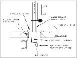
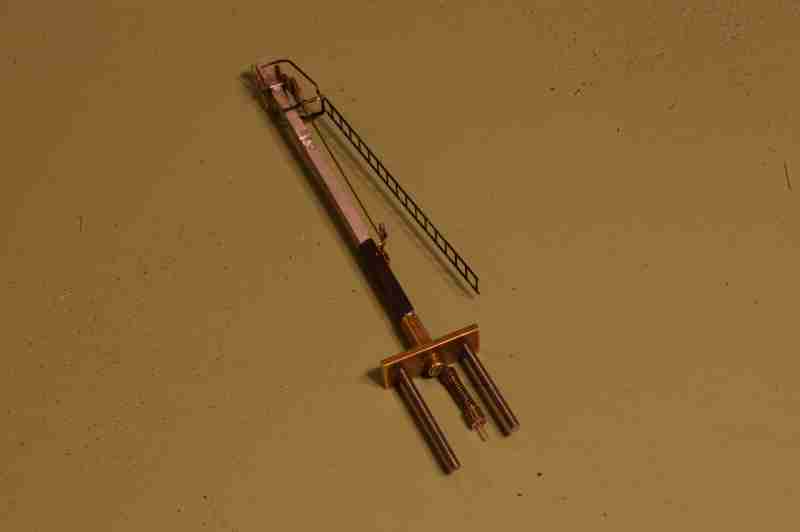
 The basic signal design is shown in the drawing and photo. The signal was mounted on a base plate, with a couple of bolts to fix the base plate to the base-
board. The signal post was fixed into a short length of brass tube, soldered to the base plate. A small diameter length of tube passed through the base-plate for the operating wire. Soldered to the bottom of this wire (below the base-board) was a brass ‘button’ which retains a compression spring. Above the base-board the signal uses the rods and balance weight as per the prototype.
With the signal detached from the base-board, it is ‘off’, and pushing upwards against the compression spring puts the signal ‘on’. The movement was supplied by a Fulgarex motor acting against a bell-crank as shown in the sketch. When installed on the layout, the bell-crank was not connected to the signal, but just pushes against the ‘button’. I threaded a long 8BA bolt into the Fulgarex slider, and adjustment of the ‘on’ position at horizontal was achieved by screwing/unscrewing this bolt.
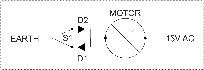 Brighton Road used control panels separate from the layout baseboards, so to minimise the amount of wiring, I used the configuration shown. There was a 15V AC supply on the layout, and I used this for motors which need to be run in both directions (turnouts, signals, gates). Diodes were used to give half-
wave rectification - positive when the switch S1 is thrown in one direction (via diode D1), and negative when thrown in the opposite direction (via diode D2). The motor therefore ran either forwards or backwards, depending on the position of switch S1. Only one wire was required between the control panel (switch S1) and the base board for each signal.
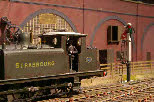
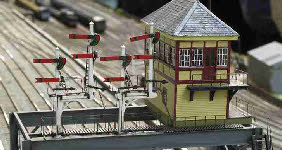
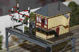
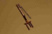
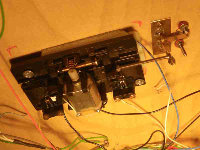
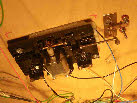 The final two photos show the signal as installed, above and below the baseboard. On the left, E1 ‘Strasbourg’ leaving the goods yard, and on the right, the Fulgarex motor, the bell-
crank and adjustable bolt as the push rod.
Running signals for Brighton Road
 Brighton Road needed quite a few running signals -
On the low level there was a home and starter, at the extreme right hand end of the layout, controlling movements on and off the layout, and there were two calling-
Brighton Road was set in quite a wide historical period, somewhere between 1900 and 1914, so it would just about have been possible to use slotted post signals, but in the end I decided to use conventional lower quadrant signals throughout, although the distant signals on the high level section were painted red as per early LBSCR practice.
All signals and turnouts on Brighton Road were operated electrically from control panels which were separate from the layout, so a reasonably efficient method of wiring up the actuators was called for. Also, because signals are fragile, I preferred a design where they could be relatively easily removable, and the main requirement was that the actuating mechanism and the signal could be removed and adjusted separately, without having to disconnect everything.
 The basic signal design is shown in the drawing and photo. The signal was mounted on a base plate, with a couple of bolts to fix the base plate to the base-
With the signal detached from the base-
 Brighton Road used control panels separate from the layout baseboards, so to minimise the amount of wiring, I used the configuration shown. There was a 15V AC supply on the layout, and I used this for motors which need to be run in both directions (turnouts, signals, gates). Diodes were used to give half-
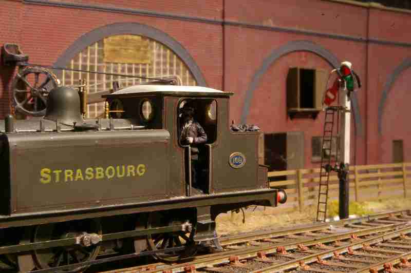
 The final two photos show the signal as installed, above and below the baseboard. On the left, E1 ‘Strasbourg’ leaving the goods yard, and on the right, the Fulgarex motor, the bell-