

The MERG forum is a very good place to ask questions and get answers about their kits and how to resolve problems. My queries to the forum yielded some quick answers - the fact that a servo requires a high instantaneous current, as much as 800mA, to get it moving. The 12v supply kit is not capable of delivering such a high current, and hence the voltage drops, causing the wayward movement of the gates.
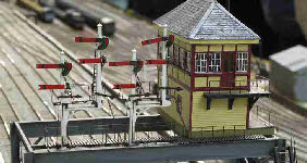
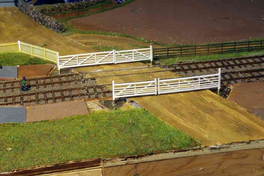
Having discovered that the problem was caused by the inadequate power supply, the solution was fairly straightforward - provide a high power (5A) 12v regulated power supply, (also supplied by MERG). The gates now work well. Old-style gates worked by hand from a capstan in the signal box take quite a long time to close - 10-15 seconds, and from my experience watching the gates at Plumpton, do not close smoothly. They tend to jerk and swing a little, very dependent on the signalman. The servo speed can be adjusted on the EZYpoints module, and 10-15 seconds is easily achievable, but at this slow speed the pulsed movement of the servos is evident. This looks fine to me, since it replicates to some extent the movement of the prototype.
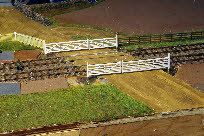 The gates at Plumpton are very skewed, so that two of the gates have to rotate about 120 deg, whilst the other two only rotate about 60 deg. Most servos have a range of almost 180 deg, and the EZYpoints kits can be made up to allow either, up to 90 deg rotation, or up to the maximum capability of the servo, with adjustments for the limits of travel at both ends of the range of movement. (The alternative kit available from MERG is the Servo4 kit, which can drive four servos, but this only allows 90 deg movement in its basic form, although it can be modified.)
One further advantage of the EZYpoints kit is that speed and limits of travel can be adjusted with a small screwdriver, whereas the Servo4 kit requires the connection of either a laptop or another MERG kit, the Servoset2. The photo above shows the three white variable resistors which control the end points and speed of rotation.
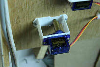
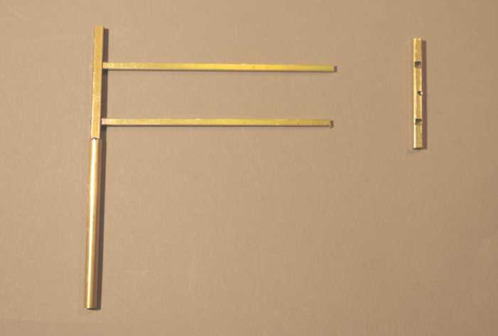
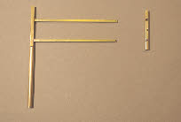 To connect the gates to the servos, I used the MERG level crossing servo mounts, but modified them as shown in the photograph right and added a brass adaptor to connect the gates to the servo. The frames of the gates are made of brass section as shown in the photo (left), and the long post engages in the hole in the top of the adaptor, held in place by the screw. The bottom of the adaptor has a piece of 0.5mm wire soldered across the large hole, and this engages in a slot on the top of the servo. Because one of the gates crosses the joint between the baseboards, it is essential that this gate can be disconnected from the servo and turned away from the edge of the baseboard to prevent damage when the layout is being packed for transport. This is easily achieved by lifting the gate slightly, disengaging the adaptor from the slot in the top of the servo, and turning the gate as required. The photo (right) links to a short video showing the various components, used both for the level crossing gates, and ground signals.
There is a short video of the gates in operation here.
(I subsequently found an alternative solution to the provision of high power 12V regulated supply, and that is to modify the MERG 12V supply by replacing the 15V capacitor with a 25V 2200mf capacitor and providing an additional heatsink for the voltage regulator. This is the same solution as I adopted to power Servo4 units, and described here).
Having discovered that the problem was caused by the inadequate power supply, the solution was fairly straightforward -
 The gates at Plumpton are very skewed, so that two of the gates have to rotate about 120 deg, whilst the other two only rotate about 60 deg. Most servos have a range of almost 180 deg, and the EZYpoints kits can be made up to allow either, up to 90 deg rotation, or up to the maximum capability of the servo, with adjustments for the limits of travel at both ends of the range of movement. (The alternative kit available from MERG is the Servo4 kit, which can drive four servos, but this only allows 90 deg movement in its basic form, although it can be modified.)
One further advantage of the EZYpoints kit is that speed and limits of travel can be adjusted with a small screwdriver, whereas the Servo4 kit requires the connection of either a laptop or another MERG kit, the Servoset2. The photo above shows the three white variable resistors which control the end points and speed of rotation.
 To connect the gates to the servos, I used the MERG level crossing servo mounts, but modified them as shown in the photograph right and added a brass adaptor to connect the gates to the servo. The frames of the gates are made of brass section as shown in the photo (left), and the long post engages in the hole in the top of the adaptor, held in place by the screw. The bottom of the adaptor has a piece of 0.5mm wire soldered across the large hole, and this engages in a slot on the top of the servo. Because one of the gates crosses the joint between the baseboards, it is essential that this gate can be disconnected from the servo and turned away from the edge of the baseboard to prevent damage when the layout is being packed for transport. This is easily achieved by lifting the gate slightly, disengaging the adaptor from the slot in the top of the servo, and turning the gate as required. The photo (right) links to a short video showing the various components, used both for the level crossing gates, and ground signals.
There is a short video of the gates in operation here.
(I subsequently found an alternative solution to the provision of high power 12V regulated supply, and that is to modify the MERG 12V supply by replacing the 15V capacitor with a 25V 2200mf capacitor and providing an additional heatsink for the voltage regulator. This is the same solution as I adopted to power Servo4 units, and described here).